Introduction #
Thank you for purchasing an Electroconcept product.
Please read carefully the following guide before using DMX controller for LED Strip 4 16-Bit Channels 10 A RISCV.
Responsibility:
Electroconcept can’t be held responsible for any damage caused by a misuse of any kind such as loss of utilizing, consumable destruction (tapes, CDs, LED Strips, etc.) or any other financial loss due to an unappropriate use of our products or any impossibility to use them; so as any wiring mistake during the installation.
Guarantee:
Electroconcept products benefit from a two years manufacturer guarantee (electronic components only, except consumable ones e.g plastic components). The product must be returned to Electroconcept postage paid and in its original package. If not, the package will be refused and returned to sender. Electroconcept company is in charge of the product restitution.
Are excluded of the guarantee benefits the followings : any damage caused by carelessness, mistake, lack of maintenance by the user (broken, burned, heated, soaked, silted up, etc.); wrong installation or misuse by the user. All our products are tested before sending to buyers. Modifications of any kind are at your own risk and out of guarantee benefits.
Technical specifications #
- Power Supply: DC + 3.5 V to + 30 V
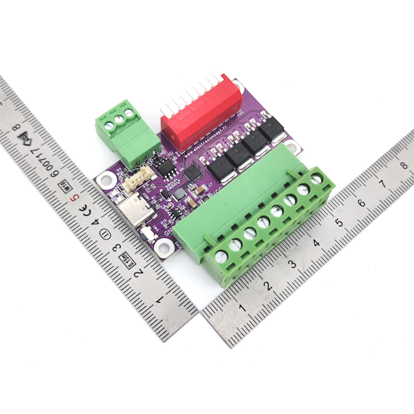
- Dimensions: 57 mm x 33 mm (plugs excluded) / 44.5 mm (plugs included)
- Channels power: 10 A per channel so about 120 W in 12 V (480 W total)
- APWM Output
- Frequency of approximately 47 Khz with a 16-Bit adjustable resolution.
Connection tips #
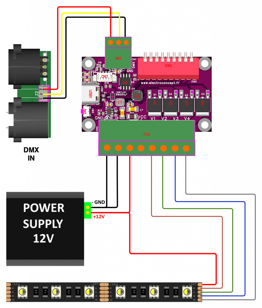
Connection for a total Intensity < 20 A :
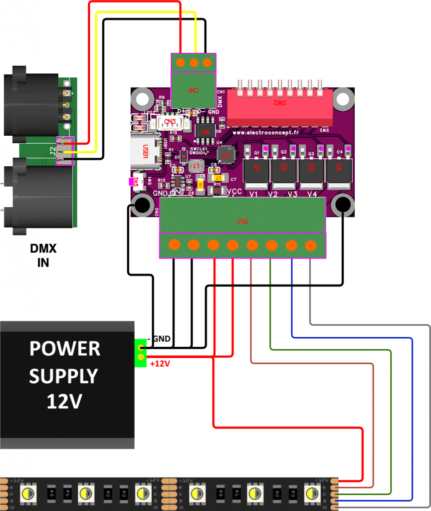
Connection for a TOTAL Intensity > 20 A:
The LED Strip V+ should be plugged directly on the power.
V- (GND) should be plugged on the two Inputs AND on the two mounting holes on the 8-pin green plug side, as shown on the diagram below.
Address and fixtures setting #
By default, if all the Dip Switch buttons are set to OFF, an automatic program starts, alternatively switching on the 4 controller Outputs.
Dip Switch addressing is a binary setting. To successfully complete these settings, you can use the address calculator provided for this purpose at the following address:
https://www.boutique-electroconcept.com/informations/reglage-dipswitch-dmx.html
DMX addressing is done with the Dip Switch or DMX tools https://dmx-tools.electroconcept.fr/ connecting the board to your computer.
- Ensure that the board for which you are making adjustments is electrically switched off,
- Open the webpage in a browser compatible with USB HID standard like Google Chrome on PC or Opera on Mac,
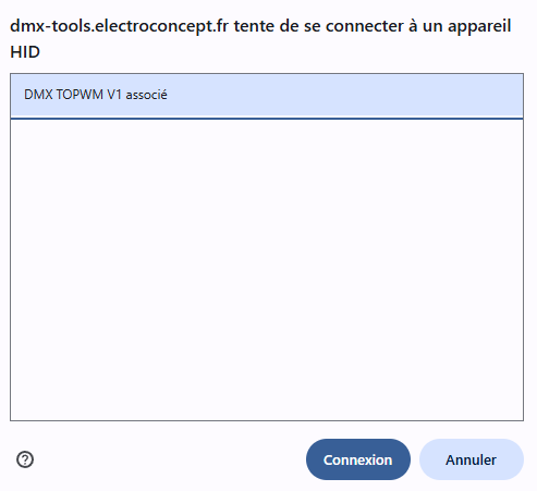
- Connect your board to your computer, then go at this address https://dmx-tools.electroconcept.fr/ and click on Connect,
- Choose your board in the pop-up window and click on Connect.
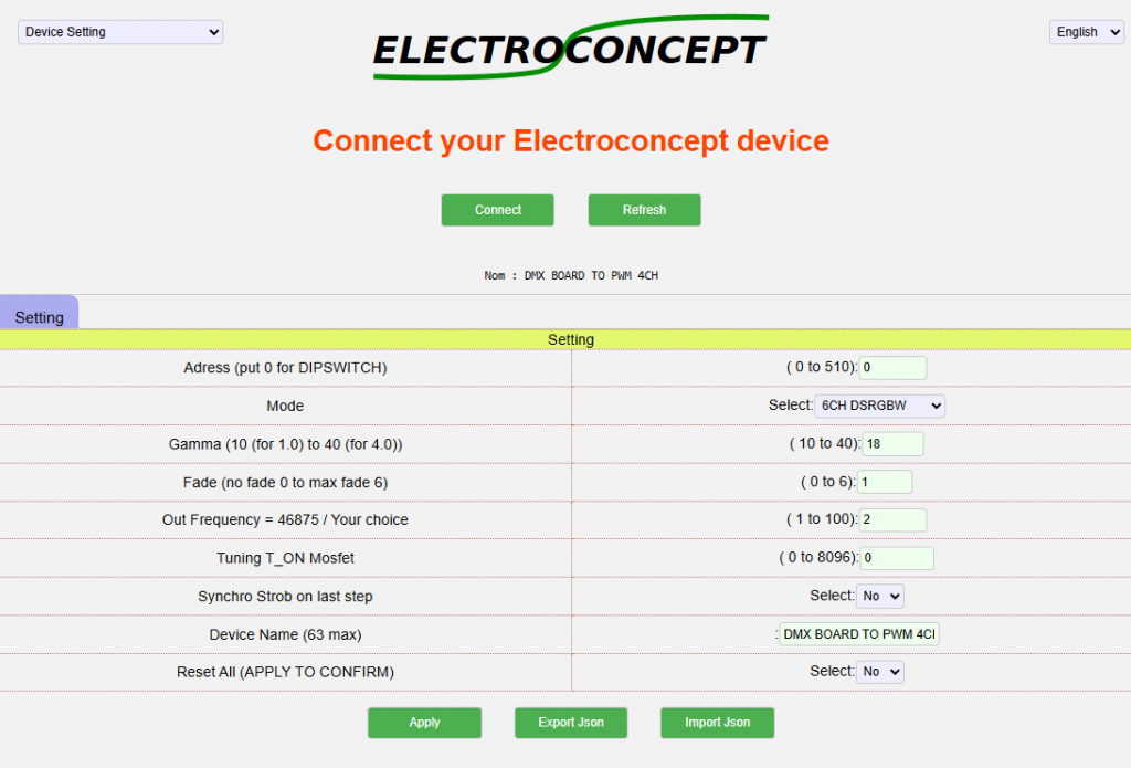
Adjustable parameters:
Address (put 0 for DIPSWITCH) : Allows to choose the address letting the Dip Switch OFF. CAUTION : Dip Switch address always has priority.
Mode : Allows to choose the control board fixture : 4 8-Bit channels, 6 Dimmer / Strob channels, 8 16-Bit channels.
Gamma (10 (for 1.0) to 40 (for 4.0)) : Allows to choose the gamma correction curve used by the control board. 10 corresponds to a linear curve, up to 40 for a gamma curve, 4.0 for an improved accuracy in small values.
Fade (no fade 0 to max fade 6) : Allows to simulate a traditional Spotlight fade effect and to smooth the gradation; 0 => OFF, 6 => very pronounced effect.
Out Frequency = 46875 / Your choice : Allows to set up the signal Output frequency from 458 Hz to 46.875 KHz.
Tuning T_ON Mosfet : Output start end adjustment parameter.
Synchro Strob on last step : Allows you to reset the strobe start to the last value received via DMX.
Device Name (63 max) : Control board name on DMX TOOLS
Reset All (APPLY TO CONFIRM) : Back to default configuration.
Details of Fixtures available on the control board:
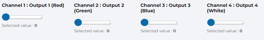
Mode 4CH RGBW
DMX channels description: 4 8-Bit channels Fixture
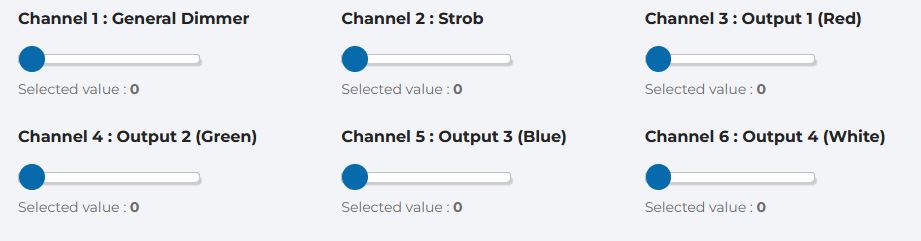
Mode 6CH DSRGBW
DMX channels description: 6 channels Fixture
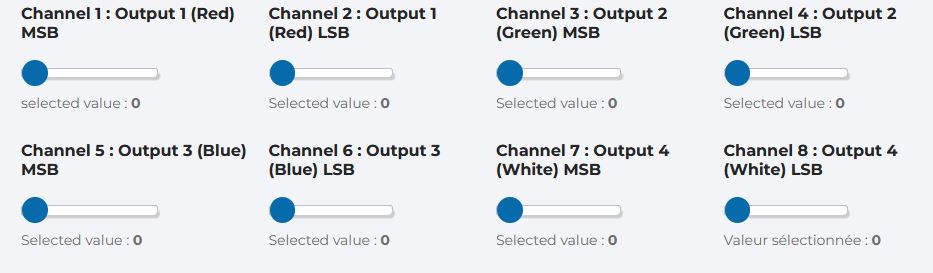
Mode 8CH Rr, Gg, Bb, Ww
Each Output setting is set to 2 channels, 1st channel is for MSB and 2nd channel for LSB.
DMX channels Mode 4 description: 8 16-Bit channels Fixture
Utilisation #
Check that your wiring complies with the connection diagram.
Select the address between 1 and 507 at which you wish to control your setup.
When your installation is powered up, the board will automatically look for a DMX signal. Once this is done, the DMX LED should light up in time with the DMX frames.
With your console is set to the operating mode (Fixture) and the assigned address, you can now control the Output levels of the DMX Controller board for 4-channel 10 A LED Strips RISCV.


