Introduction #
Thank you for purchasing an Electroconcept product.
Please read carefully the following guide before using DMX_HF_V4_2X20A Box in OEM version.
Responsibility:
Electroconcept can’t be held responsible for any damage caused by a misuse of any kind such as loss of utilizing, consumable destruction (tapes, CDs, LED Strips, etc.) or any other financial loss due to an inappropriate use of our products or any impossibility to use them; so as any wiring mistake during the installation.
Guarantee:
Electroconcept products benefit from a two years manufacturer guarantee (electronic components only, except consumable ones e.g plastic components). The product must be returned to Electroconcept postage paid and in its original package. If not, the package will be refused and returned to sender. Electroconcept company is in charge of the product restitution.
Are excluded of the guarantee benefits the followings : any damage caused by carelessness, mistake, lack of maintenance by the user (broken, burned, heated, soaked, silted up, etc.); wrong installation or misuse by the user. All our products are tested before sending to buyers. Modifications of any kind are at your own risk and out of guarantee benefits.
Technical specifications #
- Power supply: DC + 5 V to + 30 V
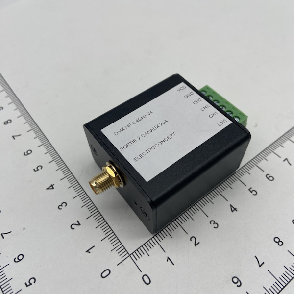
- Dimensions: 42 mm (box only)/ 65mm (box + SMA + green plug) x 40mm x 25 mm (green plug excluded)
- Channels power: 20 A per channel so about 240 W in 12 V (480 W total)
- APWM out frequency about 65Khz with 16-Bit resolution.
Connection advices #
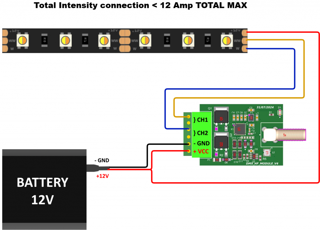
Total intensity connection < 12 A:
TOTAL intensity connection > 12 A:
LED Strips V+ must be directly connected on the power supply with a possible V+ additional connection along the LED Strip or eventually at the end.
V- (GND) must be connected to the connector Input AND to the board antenna SMA base.
LED Strips connection wires must be doubled on the green male plug and on the ledstrip (at the beginning, along the LED Strip or eventually at the end).
Address and fixture settings #
DMX and universe adressing is done with DMX HF emitter:
- Make sure the board is switched off,
- Open Assignment menu, choose DMX HF universe and DMX address wanted for DMX_HF_V4_2X20A box,
- Once the universe and the address are selected, remain in this menu and start up your device, the LED on the side box will blink 6 times quickly to confirm the assignment information has been recieved, then blink slowly to find DMX HF signal,
- Once the previous step is over, you can exit the assignment mode.
Fixture choice (Mode DMX) must be done in Assignement menu => Expert mode (>2.xD emitter is needed)
You can choose DMX mode between 0 and 5.
Mode 0: output with Gamma correction
Mode 1: linear output
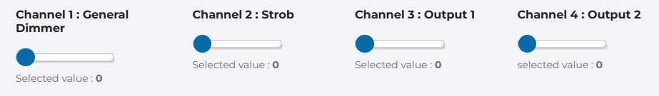
Mode 0 and mode 1 DMX channels description: 4 channels Fixture
Mode 2: output with Gamma correction
Mode 3: linear output
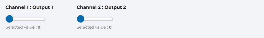
Mode 2 and mode 3 DMX channels description : 2 8-Bit channels Fixture
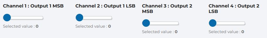
Mode 4: 16 Bits mode
Each output setting is on 2 channels, 1st channel corresponds to MSB, 2nd channel to LSM.
4 mode DMX channels description : 4 16-Bit channels Fixture
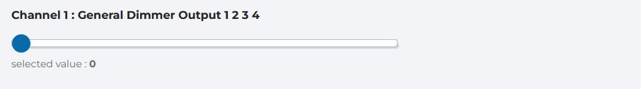
Mode 5: 1 Channel mode
Same level is sent to all Outputs.
Mode 5 DMX channels description: 1 channel Fixture
Expert Mode #
In the Expert mode, you can also add settings that modify the receiver board main behavior.
Param0: Channel 1 starting level when there is no HF
Param1: Channel 2 starting level when there is no HF
Param4 : In LED Mode: smoothing level of color changing. 0 none –> 8 extreme.
Utilisation #
When you switch on your device, the receiver board scans frequencies to find the emitter to which it is assigned, with the LED blinking slowly. Once the assignment is done, the DMX LED should light up in time with the DMX frames.
With your console set to the operating mode and assigned address, you can now control the Output levels of your DMX_HF_V4_2X20A box.


