
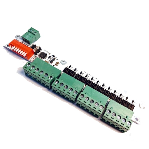
Introduction #
Thank you for purchasing an Electroconcept product.
Please read carefully the following guide before using DMX control board for LED Strips 12 channels 10 A 16-Bits (first generation).
Responsibility:
Electroconcept can’t be held responsible for any damage caused by a misuse of any kind such as loss of utilizing, consumable destruction (tapes, CDs, LED Strips, etc.) or any other financial loss due to an inappropriate use of our products or any impossibility to use them; so as any wiring mistake during the installation.
Guarantee:
Electroconcept products benefit from a two years manufacturer guarantee (electronic components only, except consumable ones e.g plastic components). The product must be returned to Electroconcept postage paid and in its original package. If not, the package will be refused and returned to sender. Electroconcept company is in charge of the product restitution.
Are excluded of the guarantee benefits the followings : any damage caused by carelessness, mistake, lack of maintenance by the user (broken, burned, heated, soaked, silted up, etc.); wrong installation or misuse by the user.
All our products are tested before sending to buyers. Modifications of any kind are at your own risk and out of guarantee benefits.
TECHNICAL SPECIFICATIONS #
- Power supply: DC + 3,5 V to + 50 V
- Dimensions : 71 mm x 22 mm x 15 mm (connectors excluded)
- Channels power: 10 A per channel or 120 W in 12 V and 1440 W total
- APWM Output frequency about 75 KHz with a possible 16-Bits resolution
Connection tips #
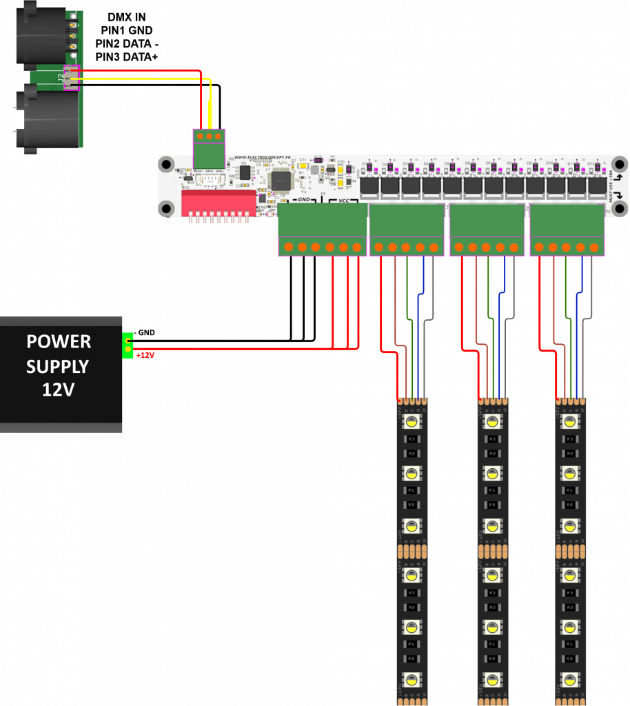
Connection for a total intensity lower than 45 A
To power the board, the V+ and V- must be connected to the connector Inputs and to the three mounting holes as shown in the connection diagram below.
The V+ of the LED strips can be connected directly to the board.
Connection for a total current exceeding 45 A
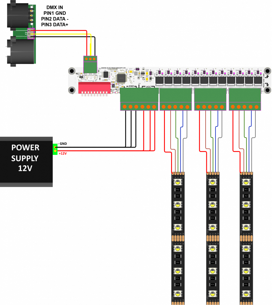
To power the board, V+ and V- must be connected to the connector Inputs and to the 3 mounting holes as shown in the connection diagram below.
The LED strips V+ are not connected directly to the board but are connected directly to the power supply.
In addition, GROUND (GND V-) reinforcements are required on the mounting holes.
Address and fixtures settings #
DMX address settings #
DMX addressing is done using the Dip Switch on the board. DMX address 0, i.e. all Dip Switch buttons set to OFF, is a test mode. This test activates all outputs at 50% power. It allows you to check all connections without the need for a DMX controller.
Addresses 505 to 511 are reserved for defining a specific mode for the card.
To help you get to grips with the possible Dip Switch settings, you can use an online calculation software available on our website: https://www.boutique-electroconcept.com/informations/reglage-dipswitch-dmx.html
Modes #
By default, DMX control board for LED Strips 12 channels 10 A 16-Bits is delivered set to 14 channels mode.
To select the number of channels corresponding to your needs, i.e wanted fixture, you should use an address between 505 and 511 at the board startup corresponding to the fixtures described below. The board stores the mode you want to use.
The LED will flash slowly to indicate that the mode has been selected and stored for future starts.
Then, switch off the board and choose a DMX address lower than 505 to use the board on the selected mode.
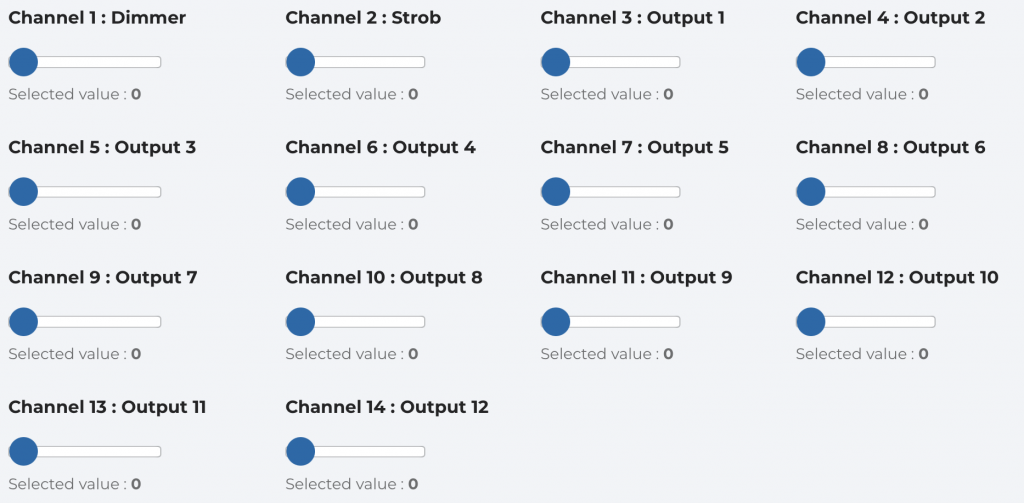
DMX channels description of modes 0 and 1. 14 channels a dimmer and a main strob Fixture:
Mode 0 includes an Output with gamma correction at address 505.
Mode 1 includes a linear Output at address 506.
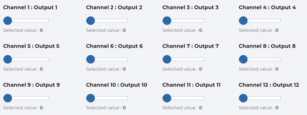
DMX channels description of modes 2 and 3. 12 channels 8-Bits Fixture:
Mode 2 includes an Output with gamma correction at address 507.
Mode 3 includes a linear Output at address 508.
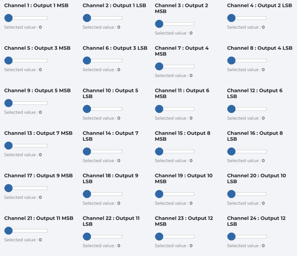
DMX channels description of mode 4 at address 509. 24 channels 16-Bits Fixture:
Each Output is adjusted on two channels, the first channel for the Most Significant Bit (MSB) and the second channel for the Least Significant Bit (LSB).
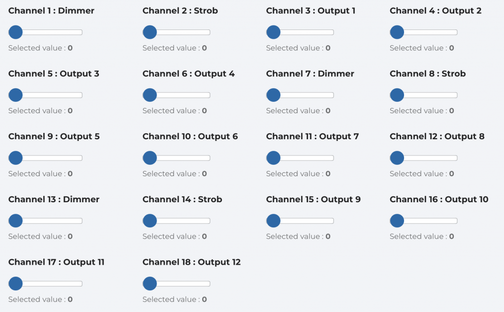
DMX channels description of modes 5 and 6. 18 channels Fixture:
Each group has its own dimmer and strob.
Mode 5 includes an Output with gamma correction at address 510.
Mode 6 includes a linear Output at address 511.
Usage #
Ensure that your wiring complies with the connection diagram.
When you switch on your device, the DMX LED should light up in time with the DMX frames.
If you use an address between 505 and 511, the card saves the mode you wish to use.
The LED flashes slowly to indicate that the mode is selected and stored for future starts.
Then switch off the board and select a DMX address lower than 505 to use the controller in the selected mode.
With your console, depending on the operating mode (Fixture) and the assigned address, you can now control the Output levels of the DMX control board for LED Strips 12 channels 10 A 16Bits (first generation).


