
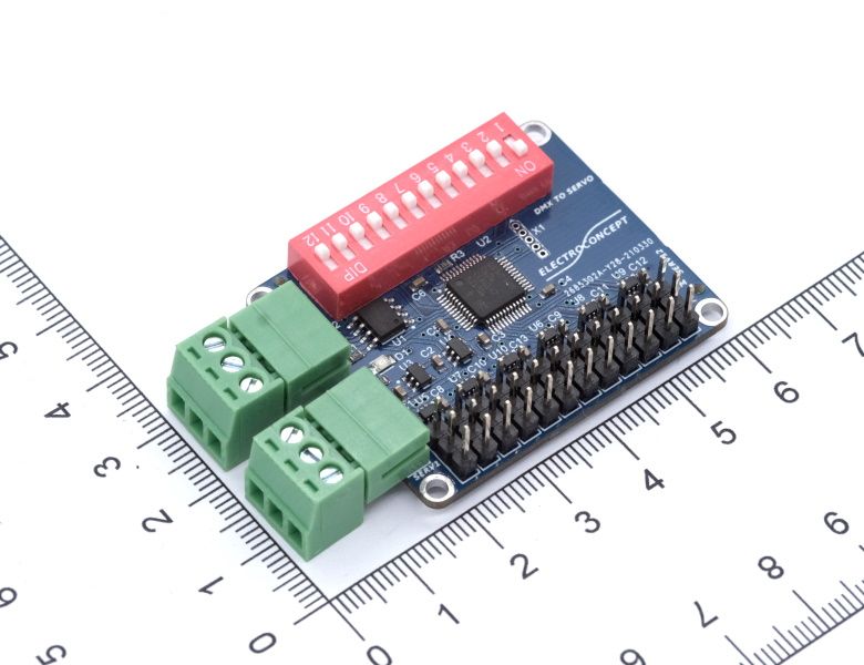
Introduction #
Thank you for purchasing an Electroconcept product.
Please read carefully the following guide before using DMX Servomotor 12 channels board (first generation).
Responsibility:
Electroconcept can’t be held responsible for any damage caused by a misuse of any kind such as loss of utilizing, consumable destruction (tapes, CDs, LED Strips, etc.) or any other financial loss due to an unappropriate use of our products or any impossibility to use them; so as any wiring mistake during the installation.
Guarantee:
Electroconcept products benefit from a two years manufacturer guarantee (electronic components only, except consumable ones e.g plastic components). The product must be returned to Electroconcept postage paid and in its original package. If not, the package will be refused and returned to sender. Electroconcept company is in charge of the product restitution.
Are excluded of the guarantee benefits the followings : any damage caused by carelessness, mistake, lack of maintenance by the user (broken, burned, heated, soaked, silted up, etc.); wrong installation or misuse by the user. All our products are tested before sending to buyers. Modifications of any kind are at your own risk and out of guarantee benefits.
Technical Specifications #
- Power supply : DC + 3.6 V à +16 V
- Power consumption : 20 mA module only, servomotors not connected
- Dimensions : 45 mm(connectors excluded) / 60 mm (connectors included) X 37 mm
- Up to 12 Servomotors per board
- PWM phase Output, adjustable timings.
Connection tips #
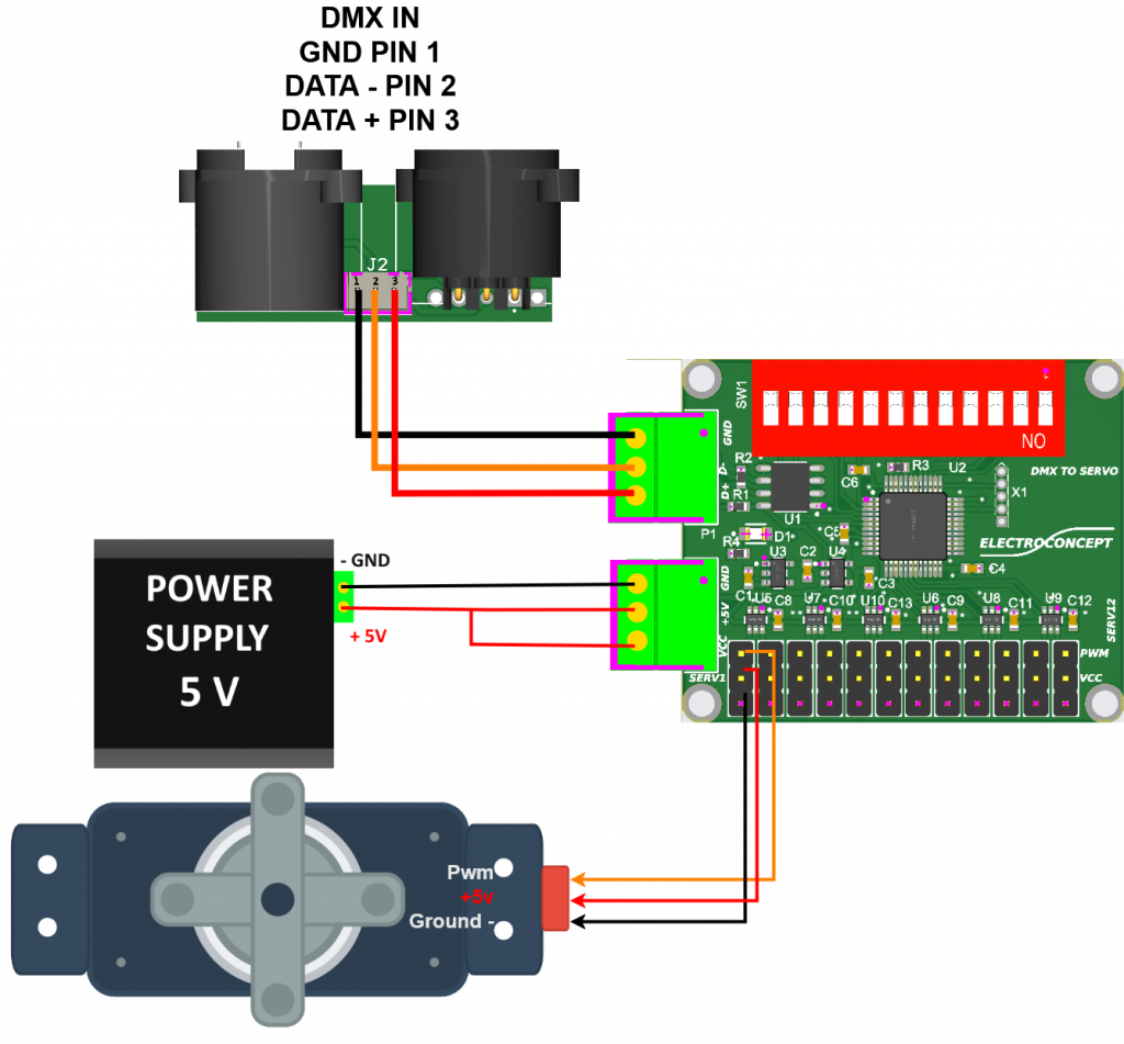
Connect VCC to power the servomotors board.
Connection for a 5 V Servomotor
The board must be connected on the 5 V AND on the VCC Input to be powered.
GND must be connected on the « – » of your direct current power supply.
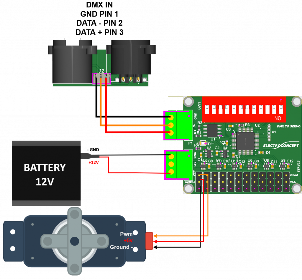
Connection for a Servomotor rated at over 5 V
The board must be connected only on VCC Input to be powered.
GND must be connected on the « – » of your direct current power supply.
Address and timings settings #
By default, Dip Switch buttons 2 to 9 are set to OFF and the Dip Switch 1 is set to ON, the board is set on DMX address 1 and is running.
Dip Switch addressing is a binary setting. To successfully complete these settings, you can use the address calculator provided for this purpose at the following address:
https://www.boutique-electroconcept.com/informations/reglage-dipswitch-dmx.html
DIP SWITCH ADVANCED SETTINGS :
Buttons 1 to 9 allow you to select the board DMX address.
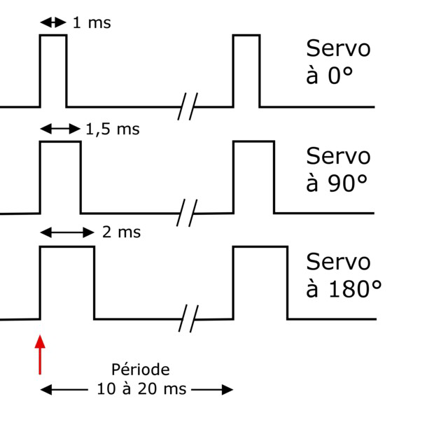
Buttons 10 and 11 allow to choose servos timings.
For example :
Adjustable settings:
DMX Address: Choice of DMX address.
Timings :
DIP 10 = 0, DIP 11 = 0 : 1 µs à 2 µs
DIP 10 = 1, DIP 11 = 0 : 0.8 µs à 2.2 µs
DIP 10 = 0, DIP 11 = 1 : 0.6 µs à 2.2 µs
DIP 10 = 1, DIP 11 = 1 : 0.5 µs à 2.5 µs
- The timing in microseconds is adjustable between 100/200 µs and 2500 µs. Please refer to the operating instructions for your servomotor to set up this pulse width.
Détails of available fixtures on the board:
Mode 8-Bit (12CH)
DMX channels Description: 12 8-Bit channels fixture
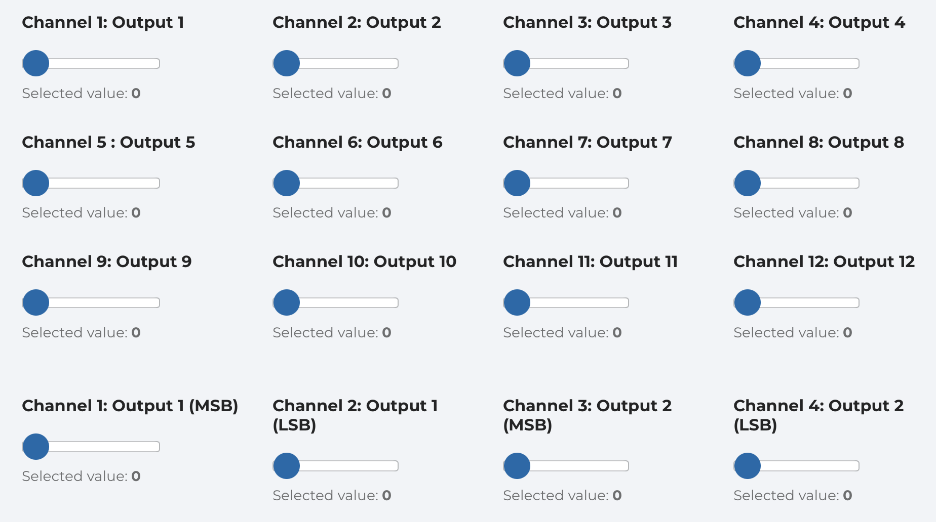
Check that your wiring complies with the connection diagram.
When your installation is powered, the board will automatically look for a DMX signal. Once this is done, the DMX LED should light up in time with the DMX frames or fixed if your DMX refresh rate is high.
When your console is set to the operating mode (Fixture) and the assigned address, you can now control the Output levels of the DMX Servomotor 12 channels ST board (first generation).


